Key Features:
Communications: WinDSX uses the TCP/IP messaging protocol with your existing LAN/WAN. Communication between the WinDSX software and DSX Controllers can be configured in many different ways. Small systems typically communicated via hard-wired connections. More complex systems may require a mixture of hard wire, fiber optics, phone modems and TCP/IP. DSX has the expertise to tie facilities together when spread across, state or even the entire country.
General Information
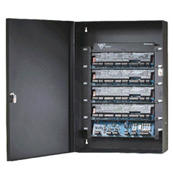
The DSX-1048PKG Intelligent Controller is an independent processing 8 door package designed to be a cost effective building block platform that allows expansion in a scalable manner. Up to 8 doors can be controlled from 1 enclosure for an efficient space saving package. The controllers are strategically placed throughout the customer location connected together with a two twisted pair cable. Each DSX-1048 operates as a fully intelligent and independent controller that retains all data necessary for system operation in its own RAM. With its integral real-time Clock and Calendar it performs Time Zone control with Holiday overrides for inputs, outputs, and cards even when communication to the PC or other controllers is not available. The DSX-1048 carries a Limited 2 Year Warranty.
Controller Architecture
The DSX-1048 Intelligent Controller may be used in conjunction with all other DSX Controllers as a Master or Slave in the controller network. Any controller may be designated as a Master or Slave controller. The Master or Slave mode of operation is determined by the panels dip switch settings. The first panel of each location is designated as the Master while all others would be considered Slaves. The Master is responsible for communications to the PC and to the Slave panels. Up to 16 – DSX-1048PKG Intelligent Controllers can be used in a single Location providing for 128 readers. Multiple Locations can be grouped for systems that require more than 128 readers/keypads.
Each DSX-1048PKG includes a DSX-1040E Enclosure, a DSX-1040CDM Communication Distribution Module and 4 DSX-1042 Intelligent Controllers. Each DSX-1048 provides 8 Reader Ports, 32 Inputs, and 16 Outputs. Each DSX-1042 has a 12 volt fused power output for its Card Readers and Keypads. The DSX-1042 contains an AM186 processor, 512K of RAM, 512K of Flash ROM, and a Real Time Clock. The DSX-1048 allows all door and field wiring connections to be made via removable terminal blocks. The DSX-1040CDM receives RS-485 communications from a possible previous panel and regenerates the 4 wire-RS485 to the next DSX-1048PKG. The DSX-1040CDM also distributes Slave Controller communication to those Slave panels located within the same enclosure.
Used in conjunction with the DSX-1048PKG Intelligent Controller is a DSX-1040PDP or Power distribution Panel. The DSX-1040PDP houses the controller and lock power supplies, backup batteries, and fused power distribution module. The DSX-1040PDP is comprised of a DSX-1040PE enclosure, an SWS-150 15V power supply for the controllers, a SWS-150[15] or [27] for either 12V or 24V locks, and a DSX-1040PDM or Power Distribution Module.
System Power
Each Controller in the DSX-1048PKG is powered from an individually fused 12 volt output from the DSX-1040CDM distribution module located in the same enclosure. The module also provides 5 volt power for those Readers and or Keypads that require it. The DSX-1040CDM receives power from the DSX-1040PDP Power Distribution Panel.
The DSX-1040PDP houses the controller and lock power supplies, backup batteries, and fused power distribution module. The DSX-1040PDP is comprised of a DSX-1040PE Enclosure, an SWS-150 15V power supply for the controllers, an SWS-150-[15] or [27] for either 12Vor 24V locks, and a DSX-1040PDM Power Distribution Module. The DSX-1040PDM performs several critical functions. First, it takes the 15V power from the SWS-150 and provides two 3.5A Class II, Power Limited, fused outputs to power the DSX-1040CDM which distributes the power to the DSX-1042 Controllers in the DSX-1048PKG. It provides a 12VBattery Charging Circuit to charge backup batteries for the controllers. It also provides a charging circuit for the optional batteries used to backup the 12 or 24 volt lock power from the SP-150 lock power supply. The Power Distribution Module has 3 N.C. Relay Outputs, two to signal Loss of AC (one for lock power and one for controller power) and one to signal Low Battery. These Outputs can be connected to spare Inputs in the DSX-1048PKG. The module also has a Battery Test Input. This Input when activated shuts off the charging circuit and load tests the battery for 1 minute. This Input can be connected to a spare Output in the DSX-1048PKG and programmed by time zone to occur when desired. The DSX-1040PDM routes Lock Power through individual fuses for each of the 8 Class II, Power Limited, outputs. The module also has an input for a Fire Override relay contact to break Lock Power and has a Fire Override Output to connect to
Reader Technologies
The DSX-1048 is compatible with Wiegand, Barium Ferrite, Proximity, Bar Code, Magnetic Stripe, Biometric, and Smart Card readers. Any combination of reader technologies may be used in the same system. A keypad may be added to most readers to create a card and/or PIN controlled entry point. The DSX-1048 is compatible with over 225 different card readers / keypads and card formats which make it the perfect panel for retrofits. Conversion modules exist for some types of other manufacturers proprietary card readers. The panel is compatible with two wire wiegand and clock and data outputs without the use of any modules. Each reader port has 3 LED open collector outputs for Door Secure, Door Open, and Access Denied/Keypad PIN Entry. This will accommodate almost any reader and LED configuration. It is possible to connect the sounder control line of most card readers directly to the Pre-Warn output for door held open annunciation.
Memory
Each Controller has a standard configuration of 512K of Flash ROM and 512K of RAM. The RAM memory allocation is dynamic between database and event storage and set for optimum use by the Host PC according to data entered for that location. Flash ROM allows for the Controllers’ operating system to be upgraded without the changing of chips (EPROMS). Having 512K of RAM eliminates the necessity of increasing the memory in controllers as the system grows. When the Controller is in service the amount of RAM and the version of ROM can be viewed from the DSX communications software.
Inputs
The DSX-1048PKG has 32 EOL supervised Inputs capable of two, three, and four state point monitoring with trouble reports. The armed status of each Input can be controlled by up to 4 Time Zones, I/O & Card Linking, and Manually from the PC. Eight Inputs are designated as Door Position and eight Inputs are designated as Exit Request Inputs for the reader controlled doors. The remaining sixteen Inputs are then left for additional monitoring points.
Outputs
The DSX-1048PKG has 16 Programmable Outputs. Eight Outputs are Form-C, 5 Amp rated relays used to control the locks for the reader controlled doors. Eight Outputs are the open collector type, both have an LED for status and are fully programmable. In addition to the 16 programmable Outputs there are 8 Pre-Warn Outputs, (1 for each door) and are used to indicate the reader controlled doors are being held open and are about to go into alarm. Once the door is opened the Output begins pulsing low starting at 1/3 of the door open too long time and changes to a steady low anytime the door is in alarm. These open collector (switched negative) outputs reset automatically when the door is closed.
Communications
The DSX-1048PKG Intelligent Controller can communicate with the WinDSX Communications Server via TCP/IP LAN communications, Direct Serial Port connection, and Dial-Up Phone Modem. TCP/IP LAN Communications can be performed from the WinDSX Comm Server PC to a Master Controller. The WinDSX Software without the use of any additional Hardware or Software will redirect what would typically be serial port communications to a TCP/IP address. A DSX-LAN(M) serial device at the Master Controller receives the communications over the LAN from the WinDSX PC and converts it to RS-232/RS-485 for the Master Controller. The end result is real time communications similar to that of a direct serial port connection.
Direct Connect Communications from the PC to the Master Controller is performed with a connection from the Host Port of the Master to a serial port of the PC. RS-232 is used for short distance connections. RS-485 communications is used when the direct serial port connection is from 50 to 4000 feet from Controller to PC. In order to communicate with the Master Controller with RS-485 communications requires two MCI modules. One DSX MCI module is placed at the PC to convert the RS-232 signal to RS-485 and a second module is placed at the Master Controller to convert the RS-485 back to RS-232. The Controller communicates with the PC at a default baud rate of 9600.
DSX Access Systems, Inc. 10731 Rockwall Road Dallas, Texas 75238 / 888-419-8353 / 214-553-6140 / www.dsxinc.com Dial-Up Modem Communications from the DSX-1042 Master Controller to the PC utilizes a DSX modem at the Controller and one at the PC. At the DSX-1042 Master, the RS-232 Host Communications Port connects to the Modem. The Modem derives its power from the DSX-1042 panel. The Controller auto-dials to the PC all Alarm and Supervisory conditions. The Controller can also be programmed to dial the PC when its event storage buffer is 80% full.
Controller Communications is handled at each DSX-1048 by a DSX-1040CDM (communications distribution module) using true point to point, regenerative, RS-485, 4-wire communications. This module has 2 RS-485 ports for in and out 4 wire communications to other Controllers. The Controller network communications is regenerated at each DSX-1040CDM allowing up to 4000 feet of distance between Controllers over two twisted pair cable. The DSX-1040CDM has 2 RS-232 Communication Ports. One is used to connect to the Master Controller and is only used in the DSX-1048PKG Enclosure where the Master Controller resides. The other RS-232 port connects to the RS-232 port of each Slave Controller in that same enclosure. DSX-1048PKG Controllers are connected in a series loop configuration unless a DSX-1035 Quadraplexor is used for Star wiring.
DataBase Downloads
The Controllers utilize a synchronized database that is maintained with the incremental and automatic or scheduled downloading of changes only. This intelligent, independent processing increases the speed of the panel’s actions and reactions, providing more stability and security to the overall system. The Controllers are downloaded with all parameters the first time they are brought on-line. Once the initial full download occurs all database changes such as the adding and deleting of card holders are sent to the Controllers by way of incremental downloads. The Controllers’ transaction buffer automatically adjusts its size to utilize any RAM not allocated
for data.
1048 Packaging Components
The DSX-1048PKG includes a DSX-1040E Enclosure, a DSX-1040CDM Communication Distribution Module and 4 – 1042 Intelligent Controllers. This provides 8 Reader Ports, 3 Inputs, and 16 Outputs. The DSX-1048 Package comes complete with 32-1K ohm EOL Resistors, Lock & Key, Wire Ties, Tamper Switch, an External Power Indicator and a DSX-1040PDP Power Distribution Panel.
The DSX-1040CDM receives RS-485 communications from a possible previous panel and regenerates the 4 wire-RS485 to the next DSX-1048PKG. The DSX-1040CDM module also distributes Slave Controller communication to the Slave panels within the same enclosure. Each DSX-1042 is powered from an individually fused 12 volt output from the DSX-1040CDM Communications Distribution Module. The DSX-1040CDM receives power from the DSX-1040PDP Power Distribution Panel.
Used in conjunction with the DSX-1048PKG is a DSX-1040PDP or Power Distribution Panel. The DSX-1040PDP houses the panel and lock power supplies, backup batteries, and fused power distribution module. The DSX-1040PDP is comprised of a DSX-1040PE Enclosure, an SWS-150 15V power supply for the Controllers, an SWS-150-[15] or [27] for either 12Vor 24Vlocks, and a DSX-1040PDM. The DSX-1040PDM performs several critical functions such as supervising Power Supplies and Batteries, distributing power through fused outputs, and providing battery charging circuits. All Outputs are Class II, Power Limited.


© Copyright 2013 - BAS Systems, Brisbane, Australia.
Website Design by FPI Marketing Pty Ltd
ASIAL Member #: 040434
Security Firm Licence: 3246224